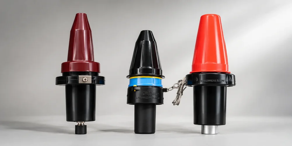
Loadbreak and deadbreak separable-connector systems support different operating duties. A loadbreak interface is designed for specified switching operations when used with the approved components, tools, and procedure. A deadbreak interface must be de-energized, isolated, tested, and grounded before it is separated. Selecting between them requires more than comparing connector size.
Quick Answer
Choose a loadbreak interface when the owner requires switching at the separable connection and the complete system is explicitly rated for that duty. Choose a deadbreak system when current is higher, switching occurs elsewhere, or the operating philosophy requires the connection to remain fixed during normal service. Always match the exact standardized interface, voltage class, current rating, and mating components.
What “Loadbreak” and “Deadbreak” Mean
| Interface duty | Permitted operation | Key limitation |
|---|---|---|
| Loadbreak | Make or break specified load current using the approved tool and procedure | Limited to the published switching and fault-close duties of the complete system |
| Deadbreak | Connect or disconnect only after the circuit is de-energized and made safe | Not designed to interrupt load current |
These terms describe operating duty, not simply connector shape. Product markings and instructions are authoritative.
Typical IEEE 386 Product Families
North American distribution systems commonly use 200 A-class loadbreak interfaces and higher-current 600 A or 900 A-class deadbreak systems. Exact voltage, continuous-current, short-time, and switching ratings vary by product and standard edition.
| Common family | Typical duty | Typical equipment connection |
|---|---|---|
| 200 A loadbreak | Load switching within published ratings | Bushing insert installed in a compatible bushing well, or an integral apparatus bushing |
| 600 A deadbreak | Higher-current fixed connection | Apparatus bushing with T-body or elbow connector |
| 900 A-class deadbreak | Higher-current applications | Matching apparatus bushing and connector system |
A bushing well plus compatible insert is a 200 A loadbreak equipment interface. It is not a 600 A well converted to 200 A. Higher-current deadbreak systems use different apparatus interfaces and connector bodies.
When Loadbreak Is the Better Fit
Consider a loadbreak system when:
- Utility operating procedures require switching at the transformer or cable connection.
- Load current and voltage are within the complete assembly’s ratings.
- Crews have the approved hot-stick tools, personal protective equipment, and training.
- The one-line design includes safe parking, grounding, testing, and feed-through arrangements.
- The owner needs sectionalizing or temporary reconfiguration at that point.
Loadbreak capability is not permission to operate in every system condition. Verify fault-close limitations, available fault current, switching sequence, and owner rules.
When Deadbreak Is the Better Fit
Consider a deadbreak system when:
- The connection’s continuous current exceeds the loadbreak product range.
- Switching is performed by a breaker, load switch, or other upstream device.
- The separable connection is opened only for installation, testing, or maintenance.
- The owner prefers a bolted or higher-current screened connection.
- The circuit design does not require energized manipulation at the connector.
Deadbreak does not mean “safe to unplug after opening a switch.” The circuit must be isolated, tested for absence of voltage, discharged, and grounded according to the approved procedure.
Selection Starts With Circuit Current, Not Transformer kVA Alone
Transformer kVA can help estimate current, but the winding voltage and phase configuration are essential:
- Three-phase current: I = kVA × 1000 / (√3 × V)
- Single-phase current: I = kVA × 1000 / V
Use the current on the winding connected to the separable interface. Then apply the transformer’s loading criteria, ambient conditions, and owner’s rating margins. Do not assign a 200 A or 600 A interface from a generic kVA table without the actual voltage and circuit design.
Compatibility Checklist
Confirm all of the following:
- Governing standard and edition
- Exact interface description and equipment-bushing drawing
- Voltage class, system grounding, and insulation level
- Continuous, short-time, and peak current requirements
- Loadbreak, deadbreak, and fault-close duties
- Connector body, bushing, insert, contact, adaptor, and cap compatibility
- Cable conductor material and cross-section
- Cable insulation diameter and screen construction
- Test point, voltage indicator, grounding, and parking accessories
- Indoor, outdoor, vault, or submersible environment
Treat products from different manufacturers as compatible only when both document conformance to the same standardized mating interface and the asset owner permits the combination.
Operating Procedure Principles
Only qualified personnel should operate medium-voltage separable connectors. A site procedure should define:
- How the source is identified and isolated
- How absence of voltage is established
- When grounds are applied
- Which hot-stick tool and operating angle are permitted
- How connectors are parked, capped, cleaned, and inspected
- How phasing and circuit identity are confirmed before reconnection
- What to do after a suspected fault-close or abnormal operation
Never use a connector as an improvised protective device or operate a deadbreak component under load.
Lifecycle Considerations
Compare the two systems using project-specific factors rather than generic percentage claims:
| Factor | Loadbreak system | Deadbreak system |
|---|---|---|
| Normal switching location | Can be at the connector within rating | Separate switching device required |
| Continuous-current range | Commonly lower | Commonly higher |
| Tooling and training | Hot-stick switching procedure | De-energized work and torque procedure |
| Component count | May include well, insert, elbow, caps, parking accessories | May include apparatus bushing, T-body/elbow, plugs, caps |
| Inspection focus | Arc-following components, contacts, cleanliness, seals | Bolted contacts, torque, cleanliness, seals |
| Replacement decision | Follow operation count and condition criteria | Follow condition, maintenance, and owner criteria |
The lowest-cost option is the one that fits the network operating model and avoids unsafe workarounds.
Frequently Asked Questions
Can a deadbreak connector be removed with load current present?
No. It must be operated only under the approved de-energized procedure.
Are all 200 A elbows loadbreak-rated?
No. Verify product marking, voltage class, interface, switching rating, and manufacturer instructions. Similar-looking components may have different duties.
Is a bushing well rated 600 A before an insert is installed?
No. A conventional bushing well and compatible insert form a 200 A-class loadbreak interface. A 600 A deadbreak system uses a different apparatus interface.
Can components from different manufacturers be mixed?
Only when standardized interface compliance and ratings are documented for the complete combination and the equipment owner allows it.
Conclusion
Loadbreak and deadbreak interfaces solve different operating problems. Base the choice on switching duty, actual circuit current, the network one-line, operating procedures, cable data, and the exact standardized mating interface. Obtain written confirmation for the complete connector assembly before installation.
For a project-specific bill of materials, send Starlight Electric the one-line diagram, equipment-bushing drawing, system ratings, switching procedure, and cable datasheet.
Related Reading
- Separable Connector Systems: Type A, Type B, Type C Interface Comparison
- Heat Shrink Cable Accessories: Working Principle and Application Scenarios
—
Need to standardize connector interfaces across a transformer fleet? Send the ratings, one-line diagram, switching rules, and cable data for a written interface schedule.
Browse Related Products
The following Starlight Electric components are referenced throughout this guide and available with full factory test reports:
- 15/20kV 200A Loadbreak Elbow Connector
- 25kV 200A Loadbreak Elbow Connector
- 15/24kV 630A Separable T Connector
- 15kV 200A High-Voltage Bushing Well
- 600A Deadbreak Oil-Immersed Bushing
- 630A 24kV Interface C Equipment Bushing