A transformer tank failure caused by overpressure is among the most expensive equipment failures in a substation. A 1000 kVA transformer that ruptures its tank is typically a total loss — the winding is soaked in oil that has been contaminated by atmospheric exposure, the tank is often deformed beyond repair, and the surrounding site may be contaminated by spilled oil. The pressure relief valve (also called a pressure relief device, PRD) is the engineered solution to this risk. This article explains how PRDs work, where they are required, and how to specify one correctly.
Quick Answer
A transformer pressure-relief device is a last line of mechanical protection that vents rapidly rising internal pressure. It does not prevent the fault or replace electrical protection. The PRD must be coordinated with tank withstand, opening and resealing characteristics, flow capacity, discharge direction, mounting, signaling, and the transformer manufacturer’s design.
Why Pressure Relief Matters
A transformer tank is filled with dielectric oil and a small headspace of nitrogen (or, in older designs, just air). Under normal operation, the internal pressure is approximately atmospheric plus the small hydrostatic head of oil. Under fault conditions, the pressure can rise rapidly:
| Fault condition | Pressure rise rate | Peak pressure |
|---|---|---|
| External short circuit (through fault) | Slow (10–30 seconds) | 5–10 psig |
| Internal arcing fault | Very fast (10–100 ms) | 30–100 psig |
| Oil expansion at cold start (winter to summer) | Slow (hours) | 1–3 psig |
| Pumped oil from sudden load drop | Moderate (1–5 seconds) | 3–5 psig |
The peak pressure during an internal arcing fault is by far the most demanding condition. Without a pressure relief device, the tank will deform or rupture within tens of milliseconds, releasing oil and possibly ejecting flaming oil from the tank.
The PRD is engineered to open at a calibrated pressure (typically 8–12 psig for distribution transformers, 10–15 psig for larger substation transformers), vent the overpressure rapidly, and reseal when the pressure returns to normal. This prevents tank rupture while keeping oil loss to a minimum.
PRD Construction
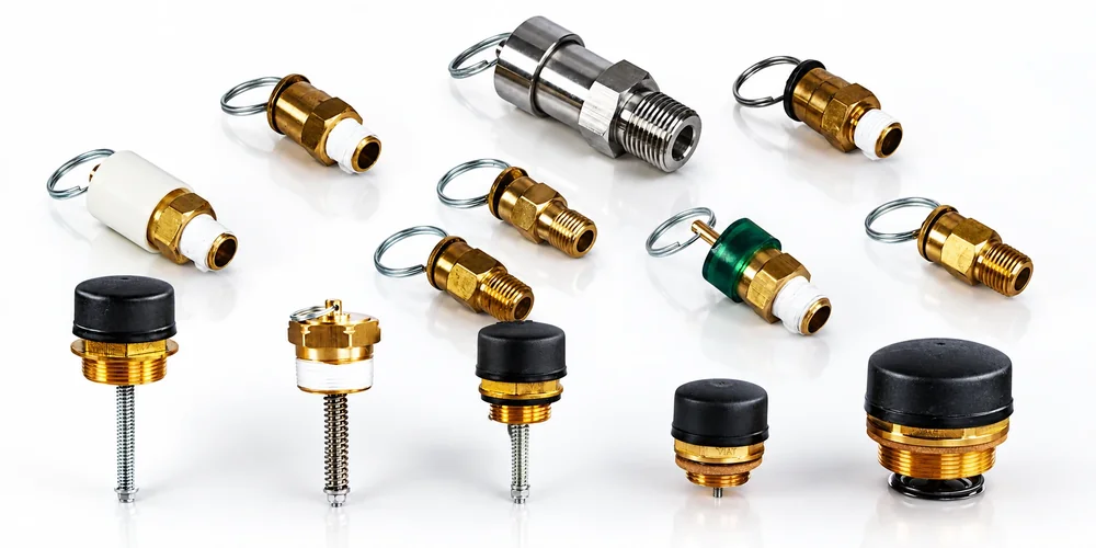
A pressure relief valve for a transformer has three functional elements:
- Spring-loaded poppet — the valve opens when the tank pressure exceeds the spring force. The spring force is calibrated at the factory to a specific set pressure.
- Soft seal (typically nitrile or Viton) — provides the leak-tight reseal after the valve closes.
- External indicator — typically a mechanical flag or a magnetic proximity sensor that signals “valve has opened” to a SCADA system or to a maintenance technician walking the line.
Most modern PRDs are also self-resetting: after the pressure drops, the spring pushes the poppet back against the seal and the valve closes automatically. Some designs include a manual reset lever that the operator can use to verify the mechanism has not seized.
Set Pressure Selection
The set pressure must be above the maximum operating pressure of the transformer (so the valve does not open under normal conditions) and below the tank deformation pressure (so the valve opens before the tank ruptures).
| Transformer type | Typical set pressure | Tank deformation pressure |
|---|---|---|
| 500–2500 kVA pad-mount | 8–10 psig (55–70 kPa) | 20–25 psig |
| 2500–10000 kVA substation | 10–15 psig (70–105 kPa) | 25–35 psig |
| Network transformer | 8–12 psig (55–85 kPa) | 20–30 psig |
| Pole-top distribution | 5–8 psig (35–55 kPa) | 15–20 psig |
A useful rule of thumb: set pressure should be 40–60 % of tank deformation pressure. This gives the operator a clear pressure margin before catastrophic tank failure.
Resealing Pressure
After the PRD opens, it must reseal when the pressure returns to normal. The resealing pressure is typically set 1–3 psig below the opening pressure to prevent chattering. A good PRD will reseal to within 0.5 psig of the resealing pressure with no detectable leakage.
For pad-mount distribution transformers, the PRD is usually field-adjustable to allow the operator to recalibrate after a fault event. For substation transformers, the PRD is usually factory-set and sealed to prevent unauthorized adjustment.
Companion Devices
The PRD is one of four pressure-related devices on a typical transformer:
| Device | Purpose | Typical location |
|---|---|---|
| Pressure relief valve (PRD) | Vents overpressure during fault | Top of tank, away from controls |
| Oil level gauge | Indicates oil level in the tank | Side of tank, at oil sight level |
| Oil temperature gauge | Indicates top-oil temperature | Side of tank, near top of winding |
| Vacuum pressure gauge | Indicates gas-space pressure (sealed-tank designs) | Top of tank, near gas space |
For pad-mount transformers, the PRD is usually a spring-loaded valve with an external flag indicator. For substation transformers, the PRD is often a broke-and-bolted rupture disk with a separate sensor to detect disk failure.
Where Pressure Relief Is Required
Pressure relief devices are mandatory on essentially every oil-immersed transformer above 500 kVA. Below 500 kVA, the requirement varies by jurisdiction:
| Jurisdiction | PRD requirement |
|---|---|
| USA (NEC 450) | Required for all oil-immersed transformers above 600 V, regardless of kVA |
| Canada (CSA C22.2) | Same as USA |
| IEC countries | Required for all oil-immersed transformers above 1000 V |
| Australia / NZ | Required for all oil-immersed transformers |
For a 25 kVA pole-top transformer, a PRD is typically not required. For a 50 kVA pad-mount, it is. The simplest rule is: if the transformer contains more than 200 L of oil, install a PRD.
Installation Notes
A PRD is mounted on the top of the tank, in a location that:
- Is above the highest expected oil level (so the device is not submerged in oil)
- Has no obstructions within 1 m (so the vented gas can escape freely)
- Is not directly above any control wiring (so vented oil does not damage the controls)
- Is away from operator access points (so vented hot gas does not impinge on personnel)
Most PRD installations include a vent pipe that directs the released gas upward and away from the operator station. The vent pipe outlet must be:
- Above the operator eye level
- Pointed away from any window or vent intake
- Terminated with a weatherproof screen to prevent insect intrusion
Inspection and Maintenance
A PRD should be inspected annually and tested every 3 years:
| Task | Interval |
|---|---|
| Visual inspection of external flag | 6 months |
| Manual operation test (verify mechanism moves freely) | 1 year |
| Set pressure verification (with portable test rig) | 3 years |
| Reseal verification (after a fault event) | As needed |
| Replacement (after 100 operations or 15 years) | As needed |
A PRD that has opened multiple times will eventually wear its seal and leak. The replacement schedule is typically 10–15 years or after a major fault event, whichever comes first.
Specifying a PRD
When specifying a PRD for a transformer, the procurement document should include:
- Set pressure (e.g., 10 psig)
- Resealing pressure (e.g., 8 psig)
- Flow capacity at set pressure + 25 % (e.g., 50 SCFM minimum)
- Tank mounting thread (typically NPT 1″, 1-1/4″, or 2″)
- Operating temperature range (typically -40 °C to +120 °C)
- Material compatibility with the transformer oil (mineral oil, ester, silicone)
- Indicator type (mechanical flag, magnetic sensor, electrical switch)
- Standards compliance (IEEE C57.12.10, IEC 60296, or both)
- Reseal leak rate (typically < 1 cc/day at resealing pressure)
- Manual reset (optional)
Frequently Asked Questions
Is a pressure gauge the same as a pressure-relief device?
No. A gauge indicates pressure; a relief device opens to discharge pressure. Some assemblies add alarms or switches, but their functions remain distinct.
Can the PRD set pressure be chosen independently?
No. It must be coordinated with the transformer tank design, liquid head, operating pressure range, test requirements, and manufacturer instructions.
What should be inspected during maintenance?
Check for leakage, corrosion, blocked discharge paths, damaged indicators or contacts, loose mounting hardware, gasket deterioration, and any evidence that the device has operated. Follow the transformer and PRD manuals.
Conclusion
The pressure relief device is the single most important safety device on an oil-immersed transformer. A correctly specified PRD prevents tank rupture during internal faults and reduces oil loss during transient overpressure events. The set pressure must be calibrated to the specific tank design, and the PRD must be inspected and tested on a regular schedule.
Starlight Electric supplies pressure relief valves, oil level gauges, oil temperature gauges, and vacuum pressure gauges for distribution and substation transformers. All devices are factory-calibrated and tested to IEEE and IEC standards, and ship with a calibration certificate.
Browse the pressure-relief and gauge family at st-trafo.com, or send your transformer rating and oil type to the engineering team for a written device package.
Related Reading
- Oil-Immersed Load Switch Applications in Distribution Networks
- Transformer Tap Changer Basics: How Rotary Tap Changers Work
—
Specifying pressure-relief and gauge devices for a transformer that will operate at high altitude or in extreme temperatures? Send your site conditions and tank deformation pressure to Starlight for a written device specification.
Browse Related Products
The following Starlight Electric components are referenced throughout this guide and available with full factory test reports:
- Transformer Pressure Relief Valve
- Transformer Oil Temperature Gauge
- Transformer Oil Level Gauge
- Transformer Vacuum Pressure Gauge