A transformer tap changer is the device that allows the operator to adjust the turns ratio of a transformer after it has been built and installed. By selecting a different tap on the primary winding, the secondary voltage can be raised or lowered in discrete steps (typically 2.5 % or 5 % per step). For distribution transformers, the tap is usually set at the factory and rarely changed. For substation power transformers and large network transformers, the tap is changed under load by an automatic voltage regulator. This article explains how rotary selector mechanisms work, distinguishes de-energized tap changers from on-load tap changers, and outlines the data needed for specification.
Quick Answer
A rotary mechanism describes how contacts select taps; it does not by itself indicate whether the device can operate under load. A de-energized tap changer must be operated only with the transformer isolated as instructed, while an on-load tap changer uses a transition system to transfer current between taps without interrupting the load. Their ratings, controls, maintenance, and costs are very different.
Why Tap Changers Exist
Power system voltage is not constant. It varies with:
- Load level (a lightly loaded feeder has higher voltage than a fully loaded feeder)
- Time of day (peak vs off-peak load)
- Power factor (reactive power flow affects voltage)
- Distributed generation (rooftop solar pushes voltage up at midday)
A transformer with a fixed turns ratio will produce a secondary voltage that varies with these factors. To keep the secondary voltage within an acceptable range (typically ±5 % of nominal), the operator adjusts the tap on the primary winding:
- Raise the tap (more primary turns) → lower secondary voltage
- Lower the tap (fewer primary turns) → higher secondary voltage
For distribution transformers, the tap is usually fixed and chosen to match the actual primary voltage at the installation site. For power transformers, the tap is changed under load by an automatic controller to maintain a constant secondary voltage.
Two Families: DETC and OLTC
Tap changers fall into two families:
| Family | Full name | When operated | Application |
|---|---|---|---|
| DETC | De-Energized Tap Changer | Transformer offline | Distribution transformer |
| OLTC | On-Load Tap Changer | Transformer in service | Power transformer |
A DETC requires the transformer to be de-energized before the tap is changed. The operator opens the upstream breaker, changes the tap, and re-closes the breaker. DETCs are simple, robust, and inexpensive, and they are standard on distribution transformers from 50 kVA to 2500 kVA.
An OLTC allows the tap to be changed while the transformer is carrying load. The OLTC mechanism includes a transition impedance (typically a resistor or reactor) that bridges between two taps during the change, so the load current is never interrupted. OLTCs are more complex, more expensive, and require regular maintenance, but they are essential for power transformers in substations where the secondary voltage must be regulated continuously.
Rotary Tap Changer Construction
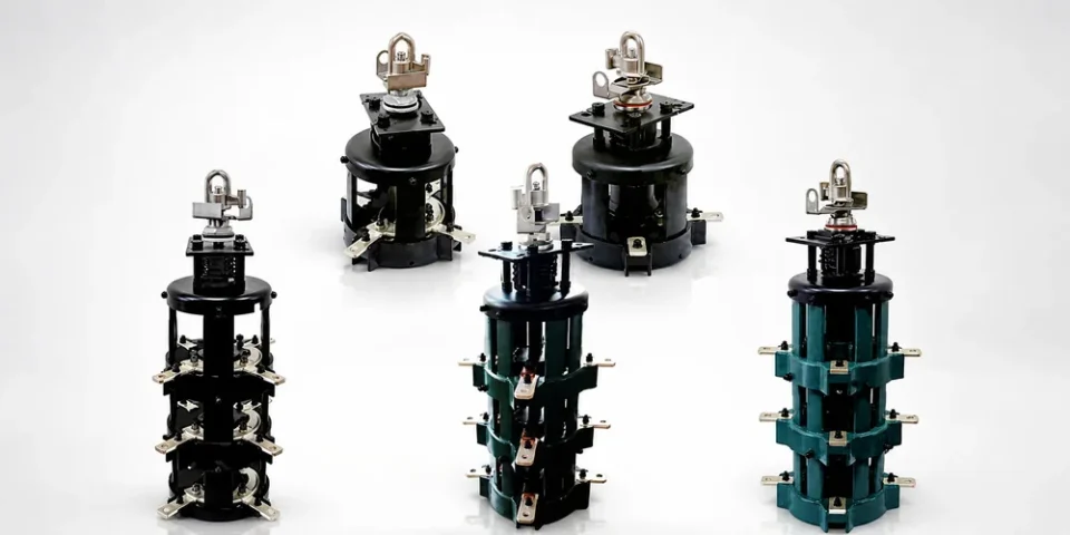
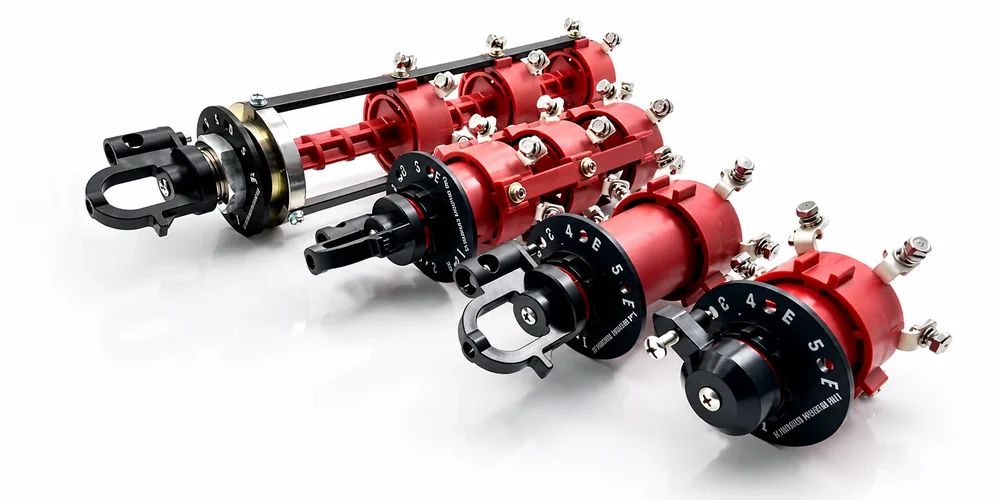
A rotary tap changer — the most common design for both DETC and OLTC — has these components:
- Tap selector — a multi-position rotary switch that engages one of the available taps on the primary winding. Typical tap counts are 5 (four steps above and below nominal) for distribution, and up to 33 for power transformers.
- Transition impedance (OLTC only) — a resistor or reactor that bridges between two taps during the changeover. Limits the circulating current to a few hundred amps.
- Drive mechanism — a hand crank (DETC) or a motor drive (OLTC) that turns the tap selector through one position per operation.
- Position indicator — a mechanical counter or digital encoder that shows the current tap position.
- Oil compartment (oil-immersed designs) — the contacts operate in transformer oil, which provides dielectric strength and arc-quenching.
For a typical 15 kV single-phase oil-immersed rotary tap changer, the assembly is a single unit that mounts on top of the transformer tank, with the contact mechanism immersed in the same oil as the windings. The external handle is on the side of the tank and is padlockable in each tap position.
Tap Voltage Steps
The standard tap voltage steps are:
| Step size | Use |
|---|---|
| 2.5 % per step | North American distribution standard |
| 5.0 % per step | Older North American, some international |
| 1.25 % per step | Power transformer OLTC |
| 1.0 % per step | Modern OLTC, IEC standard |
For a 15 kV nominal primary with five taps at 2.5 % steps, the available primary voltages are:
| Tap | Voltage |
|---|---|
| +2 (raise) | 16,125 V |
| +1 | 15,750 V |
| 0 (nominal) | 15,000 V |
| -1 | 14,250 V |
| -2 (lower) | 13,875 V |
The operator selects the tap that produces the closest-to-nominal secondary voltage at the typical load condition.
Mechanical Drive
For a DETC (distribution transformer), the drive is typically a hand-operated lever on the side of the tank. The operator:
- De-energizes the transformer (open upstream switch)
- Verifies absence of voltage with a hot-stick
- Applies grounds
- Inserts the operating handle into the drive shaft
- Rotates the handle to the desired tap position
- Removes the handle
- Removes the grounds
- Re-energizes the transformer
The handle is padlockable in each position to prevent unauthorized operation. Some utilities require the operator to record the tap position in the maintenance log after each change.
For an OLTC (power transformer), the drive is typically a motor-operated mechanism with an automatic controller. The controller monitors the secondary voltage (or the voltage on a downstream bus) and commands a tap change whenever the voltage drifts outside the deadband (typically ±0.75 % to ±1.5 %).
Contact Life
Tap changer contacts erode with every operation. The expected contact life depends on the load current and the type of OLTC:
| OLTC type | Typical operations before contact replacement |
|---|---|
| Resistor-type (standard) | 500,000 – 1,000,000 operations |
| Reactor-type | 1,000,000 – 2,000,000 operations |
| Vacuum interrupter type | 2,000,000+ operations |
For a DETC, the contact life is essentially unlimited because the operator changes the tap only a handful of times in the transformer’s service life. The DETC contacts typically last the full 30-year design life of the transformer.
Maintenance
Tap changers require periodic maintenance. The maintenance schedule depends on the type:
| Maintenance task | DETC interval | OLTC interval |
|---|---|---|
| Visual inspection of operating handle | 1 year | 6 months |
| Drive mechanism lubrication | 5 years | 1 year |
| Oil sample analysis (DGA, dielectric) | 3 years | 6 months |
| Contact resistance measurement | 10 years | 2 years |
| Internal inspection (cover removal) | 15 years | 5 years |
| Contact replacement | As needed | Per contact life estimate |
For an OLTC, the oil sample is the most important maintenance item. The oil in the OLTC compartment degrades faster than the main tank oil because the switching arcs generate gas and carbon. Dissolved gas analysis (DGA) detects arcing in the OLTC before it becomes a failure.
For a DETC, the most common issue is the operating handle seizing due to corrosion. Periodic operation (even without changing the tap) keeps the mechanism free.
Specifying a Tap Changer
When specifying a rotary tap changer, the procurement document should include:
- Type (DETC or OLTC)
- Number of positions (typically 5, 7, 9, 11, 17, 33)
- Voltage step (2.5 %, 1.25 %, 1.0 %)
- Voltage class (matching the transformer primary)
- Continuous current rating (matching the transformer primary full-load current)
- BIL rating (matching the transformer primary BIL)
- Drive type (hand crank, motor-operated, automatic controller)
- Position indicator (mechanical counter, digital encoder, SCADA output)
- Transition impedance (resistor, reactor, or vacuum interrupter) for OLTC
- Oil compatibility (mineral oil, ester, silicone)
- Standards compliance (IEEE C57.12.10, IEC 60214, or both)
Frequently Asked Questions
Can a rotary tap changer be operated under load?
Only if it is specifically designed, marked, and documented as an on-load tap changer. Most simple distribution-transformer rotary selectors are de-energized tap changers.
What tap range is common?
Many distribution designs use five positions around nominal voltage, often in 2.5% steps, but the actual range and winding connection are transformer-specific.
What data are required for specification?
Provide transformer type, winding voltage and connection, phase count, tap positions and step size, through-current, insulation level, operation duty, liquid or dry environment, mounting, handle arrangement, interlocks, and applicable standard.
Conclusion
A rotary tap changer is the mechanism that allows a transformer to adjust its turns ratio, either at the time of commissioning (DETC) or continuously during operation (OLTC). For distribution transformers, the DETC is a simple hand-operated switch that rarely needs attention. For power transformers, the OLTC is a complex electromechanical system that requires regular maintenance to ensure reliable operation.
Starlight Electric supplies 15 kV single-phase oil-immersed rotary tap changers for distribution transformers in the 50–500 kVA range, with five tap positions at 2.5 % steps, hand-crank operation, and padlockable external handle. Request the applicable test report, installation drawing, operating restrictions, and confirmation that the device rating matches the transformer design.
Browse the rotary tap changer family at st-trafo.com, or send your transformer primary voltage and required tap range to the engineering team for a written specification.
Related Reading
- Oil-Immersed Load Switch Applications in Distribution Networks
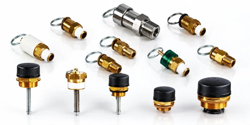
- Transformer Pressure Relief Devices: Safety Requirements and Selection
—
Specifying a rotary tap changer for a non-standard transformer rating or a custom tap range? Send your primary voltage, full-load current, and required tap positions to Starlight for a written specification including a mounting drawing.
Browse Related Products
The following Starlight Electric components are referenced throughout this guide and available with full factory test reports: