Medium-voltage separable connectors create a screened, removable connection between cable and equipment such as transformers, ring-main units, switchgear, and motors. Their mating dimensions are standardized, but the terminology is easy to misuse: Interface A, B, and C labels are commonly associated with EN 50180/EN 50181 equipment interfaces, while IEEE 386 uses a different set of interface descriptions and ratings. A purchase order should never combine the two systems as if the labels were interchangeable.
Quick Answer
Select a separable connector by matching the exact governing standard, equipment-interface designation or drawing, highest system voltage, continuous current, operating duty, and cable construction. Interface A is commonly associated with a compact 250 A-class equipment interface, Interface B with a 400 A class, and Interface C with a 630 A class; however, subtypes and manufacturer application ranges matter. Confirm the marked interface and drawing on both mating components.
Why the Interface Designation Matters
A separable connector is a coordinated system. The equipment bushing, connector body, contact, conductor adaptor, stress-control geometry, test point, earthing lead, and cable all have to work together. Two products with the same nominal voltage and current can still be incompatible because their mating dimensions, contact arrangement, insulation diameter range, or operating duty differ.
The interface designation controls three practical questions:
- Will the connector physically mate with the equipment bushing?
- Can the contact system carry the required continuous and short-time current?
- Is the completed assembly qualified for the specified voltage class and environment?
It does not, by itself, prove that a connector is loadbreak-rated or suitable for a particular cable.
Standards: EN Interfaces and IEEE 386 Are Not the Same Naming System
European equipment bushings and plug-in interfaces are commonly specified using EN 50180 and EN 50181. North American separable insulated connector systems are commonly specified to IEEE 386. Both approaches standardize mating interfaces, but they use different terminology and product conventions.
| Procurement system | Typical reference | How to specify safely |
|---|---|---|
| European / IEC-oriented equipment | EN 50180 and EN 50181 interface designation | State interface letter and subtype, Um, current, drawing, and connector standard |
| North American distribution equipment | IEEE 386 standardized interface | State voltage class, current class, loadbreak or deadbreak duty, and exact interface description |
| Custom or legacy equipment | Manufacturer drawing and part number | Supply dimensioned drawings and obtain written compatibility confirmation |
If a project uses equipment from both markets, create separate line items for each interface system. Do not translate “Interface C” into “600 A IEEE 386” without checking the equipment drawing and supplier documentation.
Interface A — Compact 250 A-Class Equipment Interface
Interface A is used where a compact separable connection is appropriate and the continuous-current requirement falls within the product’s stated application range. It is commonly encountered on smaller distribution transformers, motors, and compact switchgear.
Typical selection checks include:
- Interface A subtype and equipment-bushing drawing
- Highest voltage for equipment (Um)
- Continuous and short-time current requirements
- Straight or elbow connector layout
- Cable conductor size and material
- Cable insulation diameter, screen type, and oversheath diameter
- Indoor, outdoor, or submersible service requirements
Do not assume that the interface letter establishes switching duty. Most screened separable connectors in this family are intended to be disconnected only under the procedure stated by the manufacturer and asset owner.
Interface B — 400 A-Class Equipment Interface
Interface B provides a higher-current standardized equipment connection while remaining relatively compact. It may be encountered on distribution transformers, switchgear, and ring-main equipment where a 250 A-class interface is insufficient.
The most important checks are the exact B-interface subtype, conductor adaptor range, contact design, and equipment-bushing dimensions. A connector body may cover a range of cable insulation diameters, while the conductor contact or adaptor is selected separately for the conductor cross-section. Ordering only the connector body without these matched components can leave an incomplete installation kit.
Interface C — 630 A-Class Equipment Interface
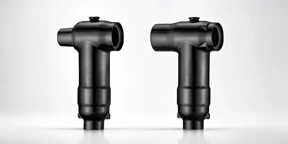
Interface C is widely used for screened separable connectors in medium-voltage distribution systems that require a 630 A-class connection. Common configurations include straight plugs, elbow connectors, and T-connectors. T-connectors can support cable branching, surge-arrester connections, or test and earthing accessories when the complete system is designed for that purpose.
Interface C products may include subtypes with different equipment-side dimensions or current capabilities. The letter alone is therefore not enough. Confirm:
- Full interface designation and dimensioned drawing
- Rated voltage and Um
- Continuous current of the complete connector system
- Short-circuit and dynamic-current ratings
- Cable range and conductor contact
- Required rear plug, insulating cap, test point, and earthing lead
- Screen continuity and touch-safe requirements
- Environmental sealing and installation orientation
Comparison Table
The table below is a procurement starting point, not a substitute for the applicable standard or product drawing.
| Parameter | Interface A | Interface B | Interface C |
|---|---|---|---|
| Common current class | 250 A | 400 A | 630 A |
| Relative size | Compact | Medium | Larger |
| Typical connector forms | Straight or elbow | Straight or elbow | Elbow, straight, or T-connector |
| Typical equipment | Smaller transformers, motors, compact switchgear | Distribution transformers and switchgear | RMUs, transformers, switchgear, cable branching systems |
| Switching duty | Verify separately | Verify separately | Verify separately |
| Interchangeability | Only with matching A interface/subtype | Only with matching B interface/subtype | Only with matching C interface/subtype |
Actual ratings and applications vary by subtype, voltage class, standard edition, and manufacturer design.
Cable Data Required for Connector Selection
The equipment interface is only half of the selection. The cable side needs equally detailed information:
- Rated voltage and highest system voltage
- Single-core or three-core construction
- Conductor material, stranded construction, and cross-section
- Conductor diameter if it is outside the normal tolerance range
- Insulation material and actual insulation diameter
- Metallic screen type and cross-section
- Armor construction, if present
- Oversheath material and diameter
- Indoor, outdoor, buried, vault, or submersible installation
- Required earthing, test-point, surge-arrester, or branch accessories
Use actual measured insulation diameter when selecting a kit for an existing cable. Nominal conductor size alone is not enough to determine the correct connector body.
Common Specification Errors
- Calling A, B, and C “IEEE 386 types.” Keep EN interface terminology separate from the IEEE 386 interface system.
- Selecting by current alone. Products with similar current ratings can have different geometry and voltage ratings.
- Ignoring the subtype or drawing. The full interface designation and dimensions are more reliable than a shortened catalog description.
- Assuming every separable connector can switch load. Operating duty must be explicitly stated and supported by the product documentation.
- Omitting cable insulation diameter. This is one of the most important dimensions for stress-control fit.
- Mixing connector bodies, contacts, and adaptors without confirmation. Treat the assembly as a qualified system.
- Using an equipment-interface standard as the only cable-accessory requirement. The complete connector still needs the applicable electrical, mechanical, and environmental qualification.
Procurement Checklist
Before issuing a purchase order, provide:
- Governing standard and edition
- Equipment manufacturer, model, and bushing drawing
- Full interface designation or exact IEEE 386 interface description
- System voltage, Um, frequency, and grounding method
- Continuous, short-time, and peak current requirements
- Loadbreak or deadbreak operating duty, if applicable
- Complete cable construction and measured insulation diameter
- Connector layout and required accessories
- Indoor, outdoor, altitude, contamination, and submersibility requirements
- Required routine and type-test documentation
Ask the connector supplier to return a written compatibility schedule that identifies every component in the assembly.
Frequently Asked Questions
Are Interface A, B, and C labels defined by IEEE 386?
Do not treat them as IEEE 386 interface names. A, B, and C terminology is commonly associated with EN 50180/EN 50181 equipment interfaces; IEEE 386 uses different standardized interface descriptions. Cite the exact standard in the purchase order.
Can connectors with the same current rating always mate?
No. The mating geometry, subtype, voltage class, contact system, accessories, and governing standard must all match.
Does “separable” mean the connector can be disconnected under load?
No. Separable describes the removable connection. Loadbreak capability must be explicitly designed, rated, marked, and operated using the approved procedure and tools.
What information is needed to select a separable connector?
Provide the equipment-bushing standard and interface, system voltage, current, switching duty, cable conductor size and material, insulation diameter, screen and armor construction, installation environment, and required accessories.
Conclusion
Interface A, B, and C designations make medium-voltage connector procurement more reliable only when they are used with the correct standard, subtype, drawings, and cable data. Keep EN interface terminology separate from IEEE 386 terminology, verify the complete assembly rather than one component, and obtain written compatibility confirmation before installation.
For a project-specific connector schedule, send Starlight Electric the equipment-bushing drawing, one-line diagram, voltage and current ratings, operating duty, and complete cable data.
Related Reading
- Deadbreak vs Loadbreak Bushing Interfaces: When to Use Each
- Heat Shrink Cable Accessories: Working Principle and Application Scenarios
—
Need a connector package for a transformer or switchgear project? Send the full interface designation or equipment drawing, cable datasheet, and one-line diagram for a written bill of materials.
Browse Related Products
The following Starlight Electric components are referenced throughout this guide and available with full factory test reports:
- 15/24kV 630A Separable T Connector
- 25kV 200A Loadbreak Elbow Connector
- 630A 24kV Interface C Equipment Bushing
- 600A Deadbreak Oil-Immersed Bushing